| The Jensen Ultraflex Or Onken Enclosure |
Данная статья сохранилась случайным образом. Источник в интернете уже не существует. Интересным является то, что изначально конструкция Дженсена предназначалась для установки в угол
и при этом боковая часть корпуса и стена помещения образовывали некое подобие рупора. Позже эта конструкция была упрощена и известна сейчас как
Jensen-Onken.
Introduction
The Bass Ultraflex enclosure is a unique design developed by Jensen, in which the loudspeaker is attached to the front panel in orthodox fashion but in wich the radiation from the back of the speaker is coupled by a large air chamber through ducts or channels to the outside. It can be termed a duct-loaded bass reflex enclosure since the operation is similar but with ducts connecting the opening ports to the inner chamber. These ducts give certain design advantage available in no other way Not to be confused with a folded horn the Bass Ultraflex design is suitable for corner or sidewall. With performance superior to any design in a similar size, its use is indicated wherever a large folded horn cannot be accomodated.
Building a 15-inch speaker Bass Ultraflex enclosure
For good results all joints must be accurately fitted and adequately glued and if not screwed, nailed with 2 ½ in. finishing nails. With the exception of the base and cleats ¾ in. plywood is used throughout.
Start by laying out the bottom of the cabinet wich measures 17 x 24 in. Note that both rear corners of the bottom are cut off at 45-deg. angle at a point 12 in. from the front. Th bottom of the cabinet is ¾ in. smaller all around than the top to allow sides, front and back to lap the edges of the bottom. Since panel A rest on top of the bottom, tit is necessary to add ¾ in.sq. filler blocks to the edge of the bottom as indicated in detail A. These filler blocks, which widen the bottom at these points, are glued and nailed to the bottom later. As with all parts, it is important that the bottom be cut out squarely since it must fit the sides, front and back tightly.
Next, cut the front for the cabinet. This measures 25½ in wide and 35¼ in. high. This makes the front 1½ in. wider than the bottom to let the front lap the sides. The 13¼ in. speaker opening is centered in the front panel on a line 16¼ in. up from the bottom. This can be cut out nicely with a jigsaw or by hand with a keyhole saw. The bottom and front of the cabinet are now joined togheter, using glue and nails, and watching to see that the bottom sets in ¾ in. on each side and flush with the bottom edge. Brace the two parts temporarily to hold them at right angles.
Next the sides are added. These measure 8¼ in. wide and 35¼ in. high; the rear edge of each is beveled 45 deg.The sides are glued and nailed securely to the edges of both the bottom and front members of the cabinet. Note that a 1 x 2 cleat is glued and screwed to the front panel on the inside 10 in. down from the top. This cleat adds additional rigidity to the front. Another cleat, 1 x 1 in. sq., is srewed and glued across the top of the front on the inside; this is used to help fasten the top of the cabinet.
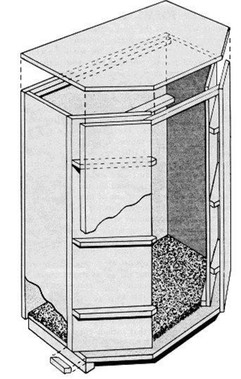
At this stage the filler blocks are added to the rear corners of the bottom. You'll notice that the ends of the block are cut 45 deg. so they will match the 45 deg. bevel on the sides as well as the angular shape of the bottom. Use glue and nailsto attach the blocks. Panels A are fitted next. These are cut ¾ in. shorter than the sides since they rest on top of the bottom. One edge of each panel is beveled 45 deg. Note that a 1 x 1 in. cleat is used to fasten each panel to the bottom of the cabinet. These cleats are placed at a 45 deg. angle on a line even with the beveled edge of the sides. The panels are glued and nailed to the beveled edges of the sides and then screwed to the cleats previously screwed to the bottom of the cabinet. Next, three ¾ in. thick spacer blocks 1-15/16 in. wide are cut to the shape and glued to the rear faces of panel A. These blocks, besidesadding rigidity to panel A and B, help support the removeble back of the cabinet. Detail B shows the approximate locations of the blocks.
Panels B are added next. These are cut 8-1/8 in. wide, and since they lap the edge of the bottom, they are made 35¼ in. high like the sides and front. Both panels are beveled 45 deg. along the outer edge. Panel B are fastened to the edges of the bottom and to the spacer block. The two panels, A and B, now form a sound passage 1-15/16 in. wide at each side of the cabinet. The top of the cabinet is cut to be even with the outside all around; nail and glue down into the edge of the plywood.
The back panel is fastened in place with screws so it may be removed easily. Note how the vertical edges are beveled 45 deg. for snug fit against the square edges of panels B. Note too that the beveled edges are faced with a strip of sponge rubber to assure a tight seal when the screws are dwìrasn tight. A 1 x 1 in. cleat, angle-cut 45 deg. at the ends, is placed across the back of the cabinet at the top. This cleat is glued and screwed securely to the underside of the top, ¾ in. in from the edge, and provides a place for driving the screws that old the back panel to the top.
Although optional, the set-back base add a finished look to the cabinet; it consists of three pieces of 2 x 2 material (actually 1-5/8 in. sq.) mitered at the corners; the base sets in ¾ in. at front and sides. All exposed nail and screw head can be sunk slightly below the surface and puttied over to conceal them. Add 1-in. thick absorption material to top and bottom as shown; jute rug padding or dense fiberglass board are recommended.
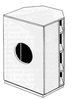
Build-in forms of the Bass Ultraflex
Many will prefer the more orthodox chest type enclosure. Obviously the orthodox chest forms are also excellent as free-standing pieces as well.
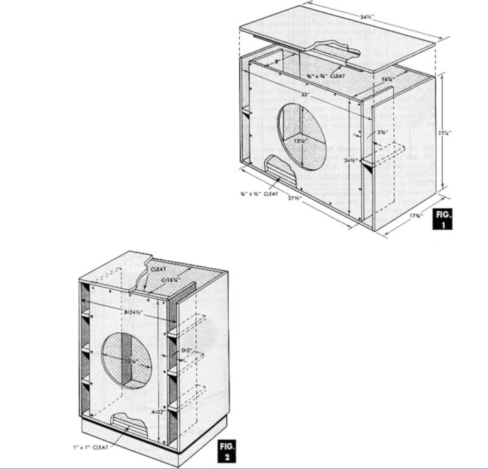
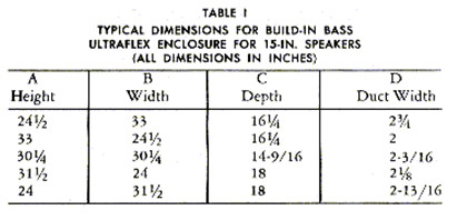
Figure 1 shows a horizontal chest version of the Bass Ultraflex enclosure. Assembly procedure is evident from the drawing as is the various panel sizes. The front baffle is shown removable for easy access when the cabinet is built in. Figure 2 shows an upright form of the Bass Ultraflex. It is now evident that the particular shape is not important. What is important is the total interior volume, the duct area and the duct length. Table 1 shows several values for the various dimensions of this basic type of enclosure. If one of these do not meet your needs simply choose inside dimensions for height A, width B and depth C so that the total interior volume A x B x C equals 13,300 cu. in. Since the duct height is the cabinet height A, calculate the duct width D so that the total duct area (two ducts) 2 x A x D equals 134 sq. in. The duct length must always be 8". It is not desirable to chose any one dimension greater than three times the smallest dimension; this encourages organ pipe resnance effects thata are undesirable. Absorption material on top and bottom is recommended just as described for the corner type Bass Ultraflex. Here then is an enclosure design you can tailor to any need.